Difference between revisions of "Control Pad (Mega Drive)"
From Sega Retro
(thanks jorge) |
|||
| Line 215: | Line 215: | ||
|} | |} | ||
| − | Bit 7 latches the value written to it. It takes approximately the equivalent of two nop instructions for | + | Bit 7 latches the value written to it. It takes approximately the equivalent of two nop instructions for other types of controllers to respond to a TH change. |
==External Links== | ==External Links== | ||
Revision as of 22:48, 13 June 2012

| |||||
| Control Pad | |||||
|---|---|---|---|---|---|
| Made for: Sega Mega Drive | |||||
| Manufacturer: Sega | |||||
|
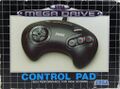
The Sega Mega Drive Control Pad (コントロールパッド) is the official controller of the Sega Mega Drive (or Sega Genesis in North America). Three button controllers are known officially as Control Pads in both North America and Europe, and SJ-3500s in Japan (following a system set up by the SG-1000). There are many "updates" and alternatives to this controller, the most notable being the Six Button Control Pad. This article covers only the basic three button variants.
Mega Drive control pads are the logical progression from Master System control pads. Copying a system set up by Nintendo, the three button Mega Drive control pad adds, as the name suggests, an extra face button (or "Trigger" as it was initially called), ![]() , to go with
, to go with ![]() ,
, ![]() and START .
and START . ![]() and
and ![]() map to
map to ![]() and
and ![]() on a Master System controller, while START eliminates the need for a pause button placed on the console unit itself.
on a Master System controller, while START eliminates the need for a pause button placed on the console unit itself.
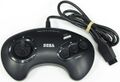
Mega Drive controllers are notable for being one of the first control pads to be ergonomically designed for the user's hands. Though improvements were made in the coming years, previous systems had cornered edges with their controllers, meaning they were often uncomfortable to hold after several hours of play. The Mega Drive controller is rounded, and has its buttons placed in easier to reach positions.
Contents
Variations
Control pads remained mostly the same across regions, but the colouring can determine the region and revision of the accessory.
Japan
SJ-3500
The first controller for the Sega Mega Drive, released in 1988. The ![]() ,
, ![]() and
and ![]() buttons are printed in red lettering and the START button is blue. The text at the top of the controller reads "Computer Video Game Control Pad". Later revisions removed the red lettering from the action buttons.
buttons are printed in red lettering and the START button is blue. The text at the top of the controller reads "Computer Video Game Control Pad". Later revisions removed the red lettering from the action buttons.
Control Pad
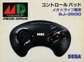
Front of box
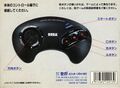
Back of box


North America
Sega Genesis Control Pad (Model No. 1650)
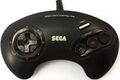
Initial Sega Genesis three-button controllers had a white START button, with red coloured text. The arrows surrounding the D-Pad are also coloured red, and the printed text in the middle reads "Sega Genesis". These controllers match the original Genesis, and were distributed with the console during its early years.
Control Pad
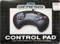
Front of box
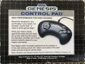
Back of box


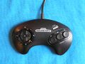
Sega Genesis Control Pad (v2) (Model No. 1650)
As the original Genesis was revised during the early 1990s, so were the controllers. The arrows were changed to white and the text was left black. The text "TRIGGER" was moved below the three buttons, and extra labels for ![]() ,
, ![]() and
and ![]() were added on top. This controller was also packaged with the Genesis 2 console.
were added on top. This controller was also packaged with the Genesis 2 console.
Early versions of this controller used the same internals as the original design, but later models have an improved D-Pad mechanism, employing a metal ball-bearing for the pad to rock on. This prevented the wear which plagued the original design, which used a plastic nub for the rocking motion and would eventually wear down with frequent use. A minor addition is a little plastic lump on the ![]() button, presumably to help users recognise where their right hand thumb was.
button, presumably to help users recognise where their right hand thumb was.

Control Pad

Sega Genesis Control Pad (v3) (Model No. 1650)
Though this controller appears to be identical to the above, it once again has an updated D-pad. This was the first iteration of Sega's two-piece D-pad mechanism, used in every official subsequent controller up to and including the Sega Saturn's. Rather than providing the rocking motion by a plastic nub or ball-bearing, there is a molded dome underneath the outside half of the D-pad which allows the D-pad to glide smoothly in a circle. This design was also plagued with wear like the first model, eventually resulting in all four directions being able to be pressed simultaneously.
Control Pad

Europe
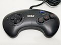
Sega Mega Drive Control Pad
Almost identical to the second Sega Genesis three-button gamepad, the first European Mega Drive controller sports a white START button, the text "SEGA" and "Mega Drive Control Pad", and red lettering on the action buttons and red-coloured arrows around the D-pad.
Control Pad
Front of box


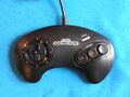
Sega Mega Drive Control Pad (revised)
Later revisions of the Mega Drive controller retain the white START button and "SEGA" text, but the red lettering and arrows were removed. The "TRIGGER" text was also moved to below the ![]() button.
button.
Control Pad

Sega Mega Drive Control Pad II
This revised version of the original Mega Drive controller was released with the revised Sega Mega Drive II, with the main change being a red START button to match the red power and reset buttons on the console. This would become the most common Mega Drive controller, as far more Model IIs were sold in Europe than Model Is.

Brazil
Asia
South Korea
Super Aladdin Boy Control Pad
The control pad that debuted along with Korea's Super Aladdin Boy is very similar to the first Japanese model. It contains a blue START button, red button text and the text "COMPUTER VIDEO GAME CONTROL PAD" printed on top. This is all rounded off with a Samsung logo in the middle.

Technical Information
The chip inside the control pad is a 74HC157. This is a high-speed CMOS quad 2-line to 1-line multiplexer. Basically, how this works is there are two inputs ( A and B ) for every output ( Y ). There are four groups like this. There is one select signal for the whole chip. When the select signal is low, the output ( Y ) is the same as input A. When the select signal is high, the output Y is the same as input B. The pinout for the chip is as follows:
| Pin 1 | Select |
| Pin 2 | 1A |
| Pin 3 | 1B |
| Pin 4 | 1Y |
| Pin 5 | 2A |
| Pin 6 | 2B |
| Pin 7 | 2Y |
| Pin 8 | Gnd |
| Pin 9 | 3Y |
| Pin 10 | 3B |
| Pin 11 | 3A |
| Pin 12 | 4Y |
| Pin 13 | 4B |
| Pin 14 | 4A |
| Pin 15 | G (? must be low) |
| Pin 16 | Vcc (+5V) |
All the controls are done with switches. Up is a switch, Down is a switch, etc. Now, I will be referring to the output of these switches later on. The output is usually high when the switch isn't pressed. When the button is pushed, the output goes low. This is accomplished by connecting the output to +5V through a 10k resistor. The button is then attached between the output and ground. It looks like this:
    +5V -----/\/\/------+--------- Output
              10k       |
                        |
               /        |
  Ground -----/  -------+
             button
             (normally open)
The line numbers are determined as follows, looking straight at the plug on the front of the Genesis the numbers are:
	1 2 3 4 5
	 6 7 8 9
| Line 1 | Up output. |
| Line 2 | Down output. These are the only two direct connections. |
| Line 3 | Pin 4 of the chip. Output 1Y. |
| Line 4 | Pin 7 of the chip. Output 2Y. |
| Line 5 | This line carries in +5V. It is connected to the +5V bus line. |
| Line 6 (TL) | Pin 9 of the chip. Output 3Y. |
| Line 7 (TH) | Pin 1 of the chip. This carries in a select signal from the Genesis. This is a signal which varies rapidly and controls which input goes through the output |
| Line 8 | Ground. This is connected to the Ground bus line. |
| Line 9 (TR) | Pin 12 of the chip. Output 4Y. |
Now for the chips pin connections:
| Pin 1 | Line 7 (select) |
| Pin 2 | Ground (1A) |
| Pin 3 | Left (1B) |
| Pin 4 | Line 3 (1Y) |
| Pin 5 | Ground (2A) |
| Pin 6 | Right (2B) |
| Pin 7 | Line 4 (2Y) |
| Pin 8 | Ground (GND) |
| Pin 9 | Line 6 (3Y) |
| Pin 10 | Button B (3B) |
| Pin 11 | Button A (3A) |
| Pin 12 | Line 9 (4Y) |
| Pin 13 | Button C (4B) |
| Pin 14 | Start (4A) |
| Pin 15 | Ground (G) |
| Pin 16 | +5V (Vcc) |
Reading
Access to controller ports is from bytes $A10003 (controller 1) and $A10005 (controller 2). TH must be set for output and the other pins for input, so bytes $A10009 and $A1000B must be set to $40 to read the respective controller.
| Bit | 7 | 6 | 5 | 4 | 3 | 2 | 1 | 0 |
|---|---|---|---|---|---|---|---|---|
| Pin | - | TH | TM | TL | R | L | D | U |
| TH = 0 | ? | 0 | S | A | 0 | 0 | D | U |
| TH = 1 | ? | 1 | C | B | R | L | D | U |
Bit 7 latches the value written to it. It takes approximately the equivalent of two nop instructions for other types of controllers to respond to a TH change.
External Links