Difference between revisions of "YM2612"
From Sega Retro
| Line 1: | Line 1: | ||
| + | {{cleanup}} | ||
{{ICBob | {{ICBob | ||
| image=Ym2612.jpg | | image=Ym2612.jpg | ||
| Line 5: | Line 6: | ||
| date= | | date= | ||
}} | }} | ||
| − | + | The '''Yamaha YM2612''' (also incorrectly called YM-2612) is a sound synthesizer integrated circuit by [[Yamaha]] [http://www.vorc.org/text/column/hally/ymxxxx.html known to have first appeared in the late 1980s]. The chip implements Yamaha Operator Type-N (OPN) frequency modulation synthesis, and is given the designation '''OPN2''', however it is not the second OPN chip — the YM2203 (OPN) and YM2608 (OPNA) are known to precede it, with possible others as well. A CMOS version, the '''YM3438'''/'''OPN2C''', was also manufactured by Yamaha. | |
By default, the chip can generate six simultaneous tones, each with their own configuration of FM operators. As with all OPN chips, the third channel can be modified to have each operator run at a different frequency — this is often called "special" or "multifrequency" mode. The sixth channel can be swapped out for a software-controlled 8-bit PCM channel mixed directly into the output waveform. Finally, there is a single LFO which acts on all FM channels, but each channel can be set to be affected by it differently. | By default, the chip can generate six simultaneous tones, each with their own configuration of FM operators. As with all OPN chips, the third channel can be modified to have each operator run at a different frequency — this is often called "special" or "multifrequency" mode. The sixth channel can be swapped out for a software-controlled 8-bit PCM channel mixed directly into the output waveform. Finally, there is a single LFO which acts on all FM channels, but each channel can be set to be affected by it differently. | ||
Revision as of 11:36, 19 October 2017
| This article needs cleanup. This article needs to be edited to conform to a higher standard of article quality. After the article has been cleaned up, you may remove this message. For help, see the How to Edit a Page article. |

|
| YM2612 |
|---|
| Designer: Yamaha |
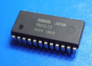
The Yamaha YM2612 (also incorrectly called YM-2612) is a sound synthesizer integrated circuit by Yamaha known to have first appeared in the late 1980s. The chip implements Yamaha Operator Type-N (OPN) frequency modulation synthesis, and is given the designation OPN2, however it is not the second OPN chip — the YM2203 (OPN) and YM2608 (OPNA) are known to precede it, with possible others as well. A CMOS version, the YM3438/OPN2C, was also manufactured by Yamaha.
By default, the chip can generate six simultaneous tones, each with their own configuration of FM operators. As with all OPN chips, the third channel can be modified to have each operator run at a different frequency — this is often called "special" or "multifrequency" mode. The sixth channel can be swapped out for a software-controlled 8-bit PCM channel mixed directly into the output waveform. Finally, there is a single LFO which acts on all FM channels, but each channel can be set to be affected by it differently.
The YM2612/YM3438 was only notably used on the Sega Mega Drive game console, Sega System 32 arcade board, and the Fujitsu FM Towns computer. However, its use on the Mega Drive meant it was also used on hardware derived from it — including arcade boards, where the YM3438 was used. Several Mega Drive 2s also used the YM3438 core.
Details
This short article is in need of work. You can help Sega Retro by adding to it.
OPN FM synthesis is similar to other forms of Yamaha FM synthesis, in that it consists of a number of operators connected in a variety of ways, each operator consisting of a modified ADSR envelope, rate scaling, frequency multiplication, detuning, and a SSG envelope generator (the YM2612 does not include the YM2149 [AY-3-8910 clone] core found in other OPN chips, but the envelope generator remains).
The YM2612 does not have a separate address and data bus. As a result, communication with the YM2612 is multiplexed on the 8-bit parallel bus. Each parameter the chip provides is accessed by first sending a register number to the chip, then the register's value. Because Yamaha's register layout only allows four channels on a single register map, the YM2612 uses two ports to access each group of three channels.
The YM2612 also contains two timers — the high frequency Timer A and lower frequency Timer B. While the YM2612 can be set to interrupt a CPU when a timer reaches zero, sadly Sega did not make this connection on the Mega Drive, requiring timers to be checked in software.
When Channel 6 is in DAC mode, the controlling CPU must stream 8-bit unsigned PCM data to the YM2612 fast enough to be played back at the optimal playback speed. The maximum sample rate depends on the sample rate of the chip, but keep in mind that register writes must be synchronized to when the chip is ready — this is checked by polling the YM2612's status register and seeing if its Busy bit is set or not.
External links
- YM3438 information, including official manuals (Japanese)
- A transcription of Sega's incomplete, sometimes incorrect YM2612 documentation from the sega2.doc file