Control Pad (Mega Drive)
From Sega Retro
| This article needs cleanup. This article needs to be edited to conform to a higher standard of article quality. After the article has been cleaned up, you may remove this message. For help, see the How to Edit a Page article. |
Over the span of the Sega Mega Drive's lifecycle, Sega released eight different types of Sega Mega Drive gamepads across its three main regions--NTSC, PAL and NTSC-J.
Contents
Types of official gamepads
Japan
| Picture | Description |
|---|---|

|
Sega Mega Drive Gamepad, JP Type I: Again, the Japanese version of the Sega Mega Drive gamepad is very much like the controllers released in the other two territories, though it has some distinct coloring differences: the |

|
JP MegaDrive 6-button pad, aka Sega Club 6 button Jr: This is the Japanese 6-button controller. It is noticeably smaller than the standard North American and European model. The blue Start button matches the color scheme of the Japanese console. Of note, its buttons were lettered in a serif style, unlike the sans-serif used previously... this font would be used again on the Sega Saturn controllers. Due to the smaller size, the controller was also offered in North America through the "Sega Club" as it was well-suited for kids' smaller hands. Sega Club was a program created by Sega of America to offer parents information about upcoming kid-friendly games. Sega Club was also responsible for "edutainment" titles and games with light difficulty for young gamers; Ecco Jr was one such title. 2-Piece D-Pad |
North America
| Picture | Description |
|---|---|

|
Sega Genesis Gamepad v1 "Model No. 1650": This is the first version of the NTSC gamepad for the Sega Genesis. It features three buttons— |

|
Sega Genesis Gamepad v2 "Model No. 1650": This is the second version of the NTSC gamepad for the Sega Genesis. It features three buttons— |

|
Sega Genesis Gamepad v3 "Model No. 1650": This is the third version of the NTSC gamepad for the Sega Genesis. It features three buttons— |

|
Sega Genesis 6-Button Gamepad "MK-1653": Following the success of arcade-to-Mega Drive games such as Street Fighter II, the six-button gamepad was released for a more arcade-like experience. This version of the gamepad featured |

|
Sega Genesis 3 Gamepad "MK-1470": This was the controller which was included with the Genesis 3 console. As the Genesis 3 was an economy model, manufacturer Majesco sourced them from a third-party manufacturer. This design became the most popular design and was simply rebranded with a different logo for each third-party company who decided to market it. It features six buttons, mode and start, and includes a switch to enable rapid-fire for all 6 buttons and slow motion via rapid pause. The design is a blatant rip-off of the Japanese 6-Button pad, but the molding does not match exactly. 2-Piece D-Pad with arguable effectiveness. |

|
Sega Megafire Gamepad, Genesis version "Model No. 1657": The Sega Megafire is an official version of the then-popular "turbo" controllers of the time, which offered autofire capabilities. The gamepad offers autofire for |
Europe
| Picture | Description |
|---|---|

|
Sega Mega Drive Gamepad, PAL Type I: The Sega Mega Drive Gamepad for PAL regions is extremely similar to the Sega Genesis gamepad; however, it has "Mega Drive Control Pad" and the Sega logo printed in lieu of the Sega Genesis logo. |

|
Sega Mega Drive Gamepad, PAL Type II: The second model of Mega Drive gamepad. Mostly identical to the type I varient, however now features a red START button instead of a white one. Model IIs were released with the Sega Mega Drive II, and would become the default controller for the years that followed. |

|
Sega Megafire Gamepad, MegaDrive version: The Sega Megafire is an official version of the then-popular "turbo" controllers of the time, which offered autofire capabilities. The gamepad offers autofire for |
Brazil
| Picture | Description |
|---|---|

|
Sega Mega Drive Gamepad, "MK-1470": A radically different design, this 6-button pad has a Turbo and slow-motion switch just like the Genesis 3 control pad. This model had a unique D-Pad implementation; a plastic spike or pillar was raised from the rear portion of the chassis and protruded through the circuit-board inside. The point of the spire is what the D-Pad rested on for its rocking motion. Of note is the model number on the rear of the pad, "MK-1470" which is the same as the Genesis 3 pad. Perhaps Sega used this as a general designation for any 6-button controllers licensed from a third-party source. The Sega logo is embossed on the rear of the controller, as well as the plug. This control pad was made by Tectoy, in Brazil. |
Technical Information
3-button gamepads
The chip inside the gamepad is a 74HC157. This is a high-speed CMOS quad 2-line to 1-line multiplexer. Basically, how this works is there are two inputs ( A and B ) for every output ( Y ). There are four groups like this. There is one select signal for the whole chip. When the select signal is low, the output ( Y ) is the same as input A. When the select signal is high, the output Y is the same as input B. The pinout for the chip is as follows:
| Pin 1 | Select |
| Pin 2 | 1A |
| Pin 3 | 1B |
| Pin 4 | 1Y |
| Pin 5 | 2A |
| Pin 6 | 2B |
| Pin 7 | 2Y |
| Pin 8 | Gnd |
| Pin 9 | 3Y |
| Pin 10 | 3B |
| Pin 11 | 3A |
| Pin 12 | 4Y |
| Pin 13 | 4B |
| Pin 14 | 4A |
| Pin 15 | G (? must be low) |
| Pin 16 | Vcc (+5V) |
All the controls are done with switches. Up is a switch, Down is a switch, etc. Now, I will be referring to the output of these switches later on. The output is usually high when the switch isn't pressed. When the button is pushed, the output goes low. This is accomplished by connecting the output to +5V through a 10k resistor. The button is then attached between the output and ground. It looks like this:
    +5V -----/\/\/------+--------- Output
              10k       |
                        |
               /        |
  Ground -----/  -------+
             button
             (normally open)
The line numbers are determined as follows, looking straight at the plug on the front of the Genesis the numbers are:
	1 2 3 4 5
	 6 7 8 9
| Line 1 | Up output. |
| Line 2 | Down output. These are the only two direct connections. |
| Line 3 | Pin 4 of the chip. Output 1Y. |
| Line 4 | Pin 7 of the chip. Output 2Y. |
| Line 5 | This line carries in +5V. It is connected to the +5V bus line. |
| Line 6 (TL) | Pin 9 of the chip. Output 3Y. |
| Line 7 (TH) | Pin 1 of the chip. This carries in a select signal from the Genesis. This is a signal which varies rapidly and controls which input goes through the output |
| Line 8 | Ground. This is connected to the Ground bus line. |
| Line 9 (TR) | Pin 12 of the chip. Output 4Y. |
Now for the chips pin connections:
| Pin 1 | Line 7 (select) |
| Pin 2 | Ground (1A) |
| Pin 3 | Left (1B) |
| Pin 4 | Line 3 (1Y) |
| Pin 5 | Ground (2A) |
| Pin 6 | Right (2B) |
| Pin 7 | Line 4 (2Y) |
| Pin 8 | Ground (GND) |
| Pin 9 | Line 6 (3Y) |
| Pin 10 | Button B (3B) |
| Pin 11 | Button A (3A) |
| Pin 12 | Line 9 (4Y) |
| Pin 13 | Button C (4B) |
| Pin 14 | Start (4A) |
| Pin 15 | Ground (G) |
| Pin 16 | +5V (Vcc) |
6-button gamepads
In order to maintain backwards-compatibility with existing games, the 6-button gamepad acts the same as the 3-button if the controller inputs are read by the program a maximum of four times per frame. Reading the 3-button gamepad takes two cycles (once with TH=1 to read Up, Down, Left, Right, B, and C; and once with TH=0 to read A and Start), and the 6-button gamepad allows this to occur twice. It then reports the state of the extra buttons when the TH line is changed after the fourth cycle.
The full controller state is read in 8 cycles:
| Cycle | TH out | TR in | TL in | D3 in | D2 in | D1 in | D0 in |
|---|---|---|---|---|---|---|---|
| 1 | HI | C | B | Right | Left | Down | Up |
| 2 | LO | Start | A | 0 | 0 | Down | Up |
| 3 | HI | C | B | Right | Left | Down | Up |
| 4 | LO | Start | A | 0 | 0 | Down | Up |
| 5 | HI | C | B | Right | Left | Down | Up |
| 6 | LO | Start | A | 0 | 0 | 0 | 0 |
| 7 | HI | C | B | Mode | X | Y | Z |
| 8 | LO | Start | A | --- | --- | --- | --- |
Note: For the 8th cycle, '---' indicates "don't care". These values are all 1 on the 6-button controller, but may be mapped to other buttons on third-party controllers. Software expecting 6-button controllers should simply ignore these values. (6-button detection should be done on the 6th cycle, which presents four 0's on the D lines.)
The controller's internal counter automatically resets after the eighth cycle. It also resets if it doesn't detect a rising-edge (0 to 1) transition on the TH line within 1.5 ms, which ensures that most games that don't support the extra buttons won't read them accidentally.
Some games incorrectly read the controller more than twice per frame, which may cause them to read the wrong set of buttons. If the Mode button is held in while starting the Genesis console, the 6-button gamepad will disable the extra buttons and act identically to a 3-button gamepad. (That is, the controller's internal counter will reset after the first two cycles instead of after eight cycles.)
Physical Scans
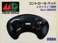
JP box (SJ-3500) (front)
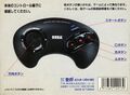
JP box (SJ-3500) (back)
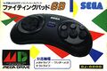
JP box (SJ-6000) (front)
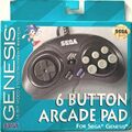
US box (MK-1470) (front)
- MDController EU Box Front.jpg
EU box (front)
EU box (MK-1653) (front)


