Difference between revisions of "Control Pad (Mega Drive)"
From Sega Retro
m (Text replacement - "[http://sega.jp/" to "[https://web.archive.org/web/*/http://sega.jp/") |
|||
| (3 intermediate revisions by 2 users not shown) | |||
| Line 5: | Line 5: | ||
| maker=[[Sega]] | | maker=[[Sega]] | ||
| madefor=[[Sega Mega Drive]] | | madefor=[[Sega Mega Drive]] | ||
| − | | releases={{ | + | | releases={{releasesMD |
| md_date_jp=1988 | | md_date_jp=1988 | ||
| md_code_jp=SJ-3500 | | md_code_jp=SJ-3500 | ||
| − | | md_rrp_jp=2,000 {{ref|http://sega.jp/fb/segahard/md/pad.html}} | + | | md_rrp_jp=2,000{{ref|http://sega.jp/fb/segahard/md/pad.html}} |
| md_date_eu=1990 | | md_date_eu=1990 | ||
| md_code_eu= | | md_code_eu= | ||
| + | | md_rrp_uk=14.99{{fileref|SegaForce UK 02.pdf|page=65}} | ||
| md_date_us=1989 | | md_date_us=1989 | ||
| md_code_us=MK-1650 | | md_code_us=MK-1650 | ||
| − | | md_date_ca= | + | | md_date_ca=1989 |
| md_code_ca=1650-22 | | md_code_ca=1650-22 | ||
}} | }} | ||
| Line 24: | Line 25: | ||
==Variations== | ==Variations== | ||
| − | Control pads remained mostly the same across regions, but the colouring can determine the region and revision of the accessory. A minor addition added in the early | + | Control pads remained mostly the same across regions, but the colouring can determine the region and revision of the accessory. A minor addition added in the early 1990s is a little plastic lump on the {{B}} button, presumably to help users recognise where their right hand thumb was. |
Early versions of this controller used the same internals as the original design, but later models have an improved D-Pad mechanism, employing a metal ball-bearing for the pad to rock on. This prevents wear which plagues the original design, which uses a plastic nub for the rocking motion and will eventually wear down with frequent use. | Early versions of this controller used the same internals as the original design, but later models have an improved D-Pad mechanism, employing a metal ball-bearing for the pad to rock on. This prevents wear which plagues the original design, which uses a plastic nub for the rocking motion and will eventually wear down with frequent use. | ||
| Line 33: | Line 34: | ||
<gallery widths="200px"> | <gallery widths="200px"> | ||
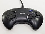
File:Pad MD JP I.jpg|SJ-3500 (Japan; 1988) | File:Pad MD JP I.jpg|SJ-3500 (Japan; 1988) | ||
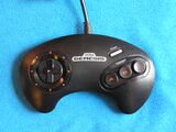
| + | File:MD JP Control Pad late model.jpg|SJ-3500 (Japan; 1991) | ||
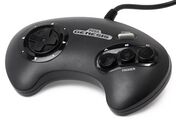
File:Pad_gen_v1.jpg|MK-1650 (US; 1989) | File:Pad_gen_v1.jpg|MK-1650 (US; 1989) | ||
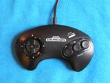
| − | File:Pad MD Gen.jpg|MK-1650 (US; | + | File:Pad MD Gen.jpg|MK-1650 (US; 1991) |
| − | File:Pad_gen_v3.jpg|MK-1650 (US; | + | File:Pad_gen_v3.jpg|MK-1650 (US; 1991) |
File:MDControlPad EU 3BV2.jpg|(Europe; 1990) | File:MDControlPad EU 3BV2.jpg|(Europe; 1990) | ||
File:Pad MD PAL I.jpg|(Europe; 1991) | File:Pad MD PAL I.jpg|(Europe; 1991) | ||
File:Pad MD PAL II.jpg|(Europe; 1993) | File:Pad MD PAL II.jpg|(Europe; 1993) | ||
| − | File:MDControlPad SK 1.jpg|(South Korea; | + | File:MDControlPad SK 1.jpg|(South Korea; 1990) |
</gallery> | </gallery> | ||
| Line 80: | Line 82: | ||
|} | |} | ||
| − | All the controls are done with switches. Up is a switch, Down is a switch, etc. | + | All the controls are done with switches. Up is a switch, Down is a switch, etc. The output is usually high when the switch isn't pressed. When the button is pushed, the output goes low. This is accomplished by connecting the output to +5V through a 10k resistor. The button is then attached between the output and ground. It looks like this: |
+5V -----/\/\/------+--------- Output | +5V -----/\/\/------+--------- Output | ||
| Line 106: | Line 108: | ||
|Line 4||Pin 7 of the chip. Output 2Y. | |Line 4||Pin 7 of the chip. Output 2Y. | ||
|- | |- | ||
| − | |Line 5||This line | + | |Line 5||This line brings in +5V. It is connected to the +5V bus line. |
|- | |- | ||
|Line 6 (TL)||Pin 9 of the chip. Output 3Y. | |Line 6 (TL)||Pin 9 of the chip. Output 3Y. | ||
|- | |- | ||
| − | |Line 7 (TH)||Pin 1 of the chip. This carries in a select signal from the Genesis. This is a signal which varies rapidly and controls which input goes through the output | + | |Line 7 (TH)||Pin 1 of the chip. This carries in a select signal from the Genesis. This is a signal which varies rapidly and controls which input goes through the output. |
|- | |- | ||
|Line 8||Ground. This is connected to the Ground bus line. | |Line 8||Ground. This is connected to the Ground bus line. | ||
| Line 118: | Line 120: | ||
| − | Now for the | + | Now for the chip's pin connections: |
{|class="prettytable" | {|class="prettytable" | ||
| Line 156: | Line 158: | ||
==Reading== | ==Reading== | ||
| − | Access to controller ports is from bytes $A10003 (controller 1) and $A10005 (controller 2). TH must be set for output and the other pins for input, so bytes $A10009 and $A1000B must be set to $40 to read the respective controller. | + | Access to the controller ports is from bytes $A10003 (controller 1) and $A10005 (controller 2). TH must be set for output and the other pins for input, so bytes $A10009 and $A1000B must be set to $40 to read the respective controller. |
{| class="prettytable" | {| class="prettytable" | ||
| Line 222: | Line 224: | ||
}}{{Scanbox | }}{{Scanbox | ||
| console=Mega Drive | | console=Mega Drive | ||
| − | | region=CA ( | + | | region=CA (1989) |
| front=ControlPad MD CA Box Front Old.jpg | | front=ControlPad MD CA Box Front Old.jpg | ||
| back= | | back= | ||
Revision as of 01:01, 24 January 2018

| |||||||||||||||||||||||||
| Control Pad | |||||||||||||||||||||||||
|---|---|---|---|---|---|---|---|---|---|---|---|---|---|---|---|---|---|---|---|---|---|---|---|---|---|
| Made for: Sega Mega Drive | |||||||||||||||||||||||||
| Manufacturer: Sega | |||||||||||||||||||||||||
|
The Sega Mega Drive Control Pad (コントロールパッド) is the official controller of the Sega Mega Drive (or Sega Genesis in North America). Three button controllers are known officially as Control Pads in both North America and Europe, and SJ-3500s in Japan (following a system set up by the SG-1000). There are many "updates" and alternatives to this controller, the most notable being the Six Button Control Pad. This article covers only the basic three button variants.
Mega Drive control pads are the logical progression from Master System control pads, replacing ![]() and
and ![]() with
with ![]() and
and ![]() respectively, while adding an extra two face buttons,
respectively, while adding an extra two face buttons, ![]() and START to bring the total number of buttons to four. Also featured is a circular D-Pad, designed to allow for movements in eight directions. Unlike Nintendo's systems, the buttons (or "triggers" as they were initially called) are arranged in alphabetical order from left to right, a practise which would continue not only with future Sega consoles, but would inspire the controllers of the Neo Geo, 3DO and Xbox lines.
and START to bring the total number of buttons to four. Also featured is a circular D-Pad, designed to allow for movements in eight directions. Unlike Nintendo's systems, the buttons (or "triggers" as they were initially called) are arranged in alphabetical order from left to right, a practise which would continue not only with future Sega consoles, but would inspire the controllers of the Neo Geo, 3DO and Xbox lines.
Mega Drive controllers are notable for being one of the first control pads to be ergonomically designed for the user's hands. Though improvements were made in the coming years, previous systems had cornered edges with their controllers, meaning they were often uncomfortable to hold after several hours of play. The Mega Drive controller is rounded, and has its buttons placed in easier to reach positions.
Variations
Control pads remained mostly the same across regions, but the colouring can determine the region and revision of the accessory. A minor addition added in the early 1990s is a little plastic lump on the ![]() button, presumably to help users recognise where their right hand thumb was.
button, presumably to help users recognise where their right hand thumb was.
Early versions of this controller used the same internals as the original design, but later models have an improved D-Pad mechanism, employing a metal ball-bearing for the pad to rock on. This prevents wear which plagues the original design, which uses a plastic nub for the rocking motion and will eventually wear down with frequent use.

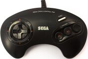
SJ-3500 (Japan; 1988)
SJ-3500 (Japan; 1991)
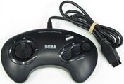
MK-1650 (US; 1989)
MK-1650 (US; 1991)
MK-1650 (US; 1991)
(Europe; 1990)
(Europe; 1991)
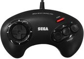
(Europe; 1993)
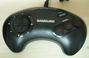
(South Korea; 1990)


Technical Information
The chip inside the control pad is a 74HC157. This is a high-speed CMOS quad 2-line to 1-line multiplexer. Basically, how this works is there are two inputs ( A and B ) for every output ( Y ). There are four groups like this. There is one select signal for the whole chip. When the select signal is low, the output ( Y ) is the same as input A. When the select signal is high, the output Y is the same as input B. The pinout for the chip is as follows:
| Pin 1 | Select |
| Pin 2 | 1A |
| Pin 3 | 1B |
| Pin 4 | 1Y |
| Pin 5 | 2A |
| Pin 6 | 2B |
| Pin 7 | 2Y |
| Pin 8 | Gnd |
| Pin 9 | 3Y |
| Pin 10 | 3B |
| Pin 11 | 3A |
| Pin 12 | 4Y |
| Pin 13 | 4B |
| Pin 14 | 4A |
| Pin 15 | G (? must be low) |
| Pin 16 | Vcc (+5V) |
All the controls are done with switches. Up is a switch, Down is a switch, etc. The output is usually high when the switch isn't pressed. When the button is pushed, the output goes low. This is accomplished by connecting the output to +5V through a 10k resistor. The button is then attached between the output and ground. It looks like this:
    +5V -----/\/\/------+--------- Output
              10k       |
                        |
               /        |
  Ground -----/  -------+
             button
             (normally open)
The line numbers are determined as follows, looking straight at the plug on the front of the Genesis the numbers are:
	1 2 3 4 5
	 6 7 8 9
| Line 1 | Up output. |
| Line 2 | Down output. These are the only two direct connections. |
| Line 3 | Pin 4 of the chip. Output 1Y. |
| Line 4 | Pin 7 of the chip. Output 2Y. |
| Line 5 | This line brings in +5V. It is connected to the +5V bus line. |
| Line 6 (TL) | Pin 9 of the chip. Output 3Y. |
| Line 7 (TH) | Pin 1 of the chip. This carries in a select signal from the Genesis. This is a signal which varies rapidly and controls which input goes through the output. |
| Line 8 | Ground. This is connected to the Ground bus line. |
| Line 9 (TR) | Pin 12 of the chip. Output 4Y. |
Now for the chip's pin connections:
| Pin 1 | Line 7 (select) |
| Pin 2 | Ground (1A) |
| Pin 3 | Left (1B) |
| Pin 4 | Line 3 (1Y) |
| Pin 5 | Ground (2A) |
| Pin 6 | Right (2B) |
| Pin 7 | Line 4 (2Y) |
| Pin 8 | Ground (GND) |
| Pin 9 | Line 6 (3Y) |
| Pin 10 | Button B (3B) |
| Pin 11 | Button A (3A) |
| Pin 12 | Line 9 (4Y) |
| Pin 13 | Button C (4B) |
| Pin 14 | Start (4A) |
| Pin 15 | Ground (G) |
| Pin 16 | +5V (Vcc) |
Reading
Access to the controller ports is from bytes $A10003 (controller 1) and $A10005 (controller 2). TH must be set for output and the other pins for input, so bytes $A10009 and $A1000B must be set to $40 to read the respective controller.
| Bit | 7 | 6 | 5 | 4 | 3 | 2 | 1 | 0 |
|---|---|---|---|---|---|---|---|---|
| Pin | - | TH | TL | TR | R | L | D | U |
| TH = 0 | ? | 0 | S | A | 0 | 0 | D | U |
| TH = 1 | ? | 1 | C | B | R | L | D | U |
Bit 7 latches the value written to it. It takes approximately the equivalent of two nop instructions for other types of controllers (such as the six-button controller) to respond to a TH change.
External links
Physical scans
| Mega Drive, US (1989) |
|---|
  Cover
|
| Mega Drive, US (1992) |
|---|
  Cover
|
| Mega Drive, US (1993) |
|---|
 Cover
|
| Mega Drive, EU (1990) |
|---|
 Cover
|
| Mega Drive, EU (1993) |
|---|
  Cover
|
| Mega Drive, JP |
|---|
  Cover
|
| Mega Drive, CA (1989) |
|---|
 Cover
|
| Mega Drive, CA (1993) |
|---|
  Cover
|